

DC Chokes
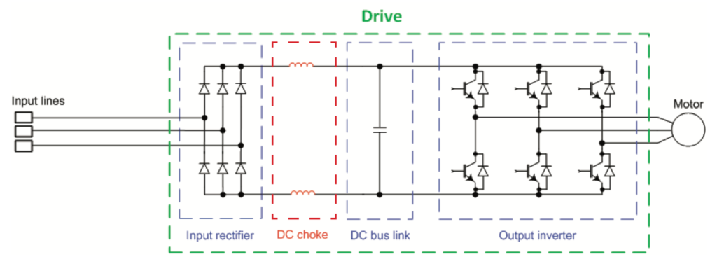
In variable frequency drives (VFDs), inductors can also be placed after the drive’s input diodes, between the input rectifier and the DC bus link. In this configuration, the inductive device is referred to as a DC bus choke, DC link choke, or DC reactor. DC bus chokes are typically built into the drive and can be installed in pairs, with one on the positive bus and one on the negative bus, or with just one device on either the positive or negative bus.
DC bus chokes are installed between the input diodes of the rectifier and the DC bus link. In this diagram, there are two DC bus chokes: one on the positive bus and one on the negative bus.

ike an AC line reactor, a DC bus choke limits the peak value of the line (supply) current, which mitigates harmonics transmitted from the line — especially the 5th and 7th harmonics. This is important because the 5th and 7th harmonics are the main contributors to total current harmonic distortion, and DC bus chokes do a better job of attenuating these harmonics than AC line reactors do. And DC bus chokes add the necessary impedance to reduce harmonics without causing the noticeable drop in voltage on the DC bus that AC line reactors typically cause. (Lowering the voltage on the DC bus limits the maximum voltage available to operate the motor, which can increase motor current and cause the motor to slip.)
DC bus chokes also help mitigate the negative effects of voltage disturbances — especially voltage dips, or sags. After a voltage sag occurs, the DC bus capacitor needs to be recharged to match the level of the source voltage. But voltage cannot change instantly in a capacitor, so an immediate inrush of current attempts to stabilize the capacitor voltage. Normally, there is a precharge circuit that limits this current, but after a voltage sag or short interruption, the precharge circuit is not available. The DC choke resists this high current inrush and protects the rectifiers and DC bus capacitors.
The main drawback to a DC bus choke especially in comparison to an AC line reactor is that a DC bus choke’s location after the input diodes prevents it from protecting the rectifier against voltage surges from the AC line supply. Hence another reason why using an AC line reactor (which does protect the rectifier from AC line surges) in combination with a DC bus choke can be beneficial.
Product Features
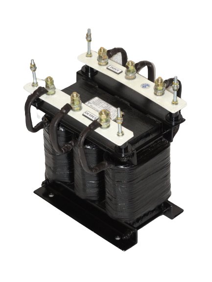
- Enclosed coils completely enclose the Line Chokes coils against moisture, dirt, dust, and industrial contaminants for maximum protection in industrial environments.
- Mounting Clamps are made of heavy steel to add strength to core construction and provide stability. Slotted mounting feet permit easy and flexible installation.
- Attractive epoxy coated black matte finish, easy-to-read label with complete technical details.
- Constructed with high quality silicon steel laminations to minimize core losses and increase performance and efficiency. The core is constructed using the “Hole-Less” method thus minimising the magnetic reluctance and decreasing the No-Load Current (NLC) and No-load Watt Losses. This will help give a performance with minimum vibration and humming Sound.
- Super Enamelled Copper or Aluminium wire of the highest quality assures efficient operation.
- Every Line Reactor is tested at a full rated current. This enables us to determine the exact Airgap required and also indicate the functioning of the Inductor at rated current.
Product Features
- Current Capacity: From 1 Amps to 1000 Amps
- Inductance: As per requirement
- Frequency: 0 – 400 Hz
- Linearity: As per requirement. At least 100% for Line Side Chokes.
- Conductor Type:
- Copper
- Aluminium
- Conductor Covering Type:
- Enamelled ‘F’ Class
- Enamelled ‘H’ Class
- Paper Covered
- Fiber Glass Covered
- Enamelled Conductor Covered in Fiber Glass
- Core Type: Cold Rolled Grain Oriented (CRGO) Laminated Silicon Steel
- Rectangular Strips
- E-I Type for Small reactors
- Varnishing Type: Vacuum Pressure Impregnated and Epoxy Coated
- Terminal Type: Wago, Phoenix, Brass Bolts, Copper Busbars
- Clamping: Solid Angles and ‘C’ Channel
- Clamping Bolts: High Tensile Bolts
