Table of Contents
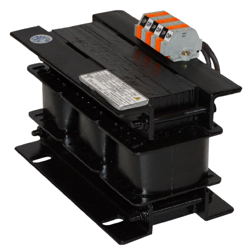
Input Line Reactors
The addition of a line reactor, sometimes known as a choke or inductor, helps protect your equipment from input power disruptions that damage the drive.
Line reactors are electro-magnetic devices which consist of a steel core wrapped with copper coils. The coils form a magnetic field which current flows through limiting the rate of rise of current, reducing harmonics and protecting additional electrical devices. There are generally two types of line reactors used with VFDs; AC & DC.
W
hen a reactor is installed between the power system and the VFD, it is known as an AC line reactor. When a DC reactor is inserted into the DC link of a drive, it is known as a DC link reactor.
Both AC and DC reactors act as harmonic current limiters but the AC reactor protects more equipment due to being installed between the VFD and power source limiting exposure to power system surges and fluctuations. This limits exposure to power system surges and fluctuations. Reactors can prevent overvoltage trips, increase the reliability and life span of the VFD, improve total power factor, and reduce nuisance tripping.
Product Features
- Enclosed coils completely enclose the Line Chokes coils against moisture, dirt, dust, and industrial contaminants for maximum protection in industrial environments.
- Mounting Clamps are made of heavy steel to add strength to core construction and provide stability. Slotted mounting feet permit easy and flexible installation.
- Attractive epoxy coated black matte finish, easy-to-read label with complete technical details.
- Constructed with high-quality silicon steel laminations to minimize core losses and increase performance and efficiency. The core is constructed using the “Hole-Less” method thus minimising the magnetic reluctance and decreasing the No-Load Current (NLC) and No-load Watt Losses. This will help give a performance with minimum vibration and humming Sound.
- Super Enamelled Copper or Aluminium wire of the highest quality assures efficient operation.
- Every Line Reactor is tested at a full rated current. This enables us to determine the exact Airgap required and also indicate the functioning of the Inductor at rated current.
Product Classifications
- Current Capacity: From 1 Amps to 1000 Amps
- Inductance: As per requirement
- Frequency: 0 – 400 Hz
- Linearity: As per requirement. At least 100% for Line Side Chokes.
- Conductor Type:
- Copper
- Aluminium
- Conductor Covering Type:
- Enamelled ‘F’ Class
- Enamelled ‘H’ Class
- Paper Covered
- Fiber Glass Covered
- Enamelled Conductor Covered in Fiber Glass
- Core Type: Cold Rolled Grain Oriented (CRGO) Laminated Silicon Steel
- Rectangular Strips
- E-I Type for Small reactors
- Varnishing Type: Vacuum Pressure Impregnated and Epoxy Coated
- Terminal Type: Wago, Phoenix, Brass Bolts, Copper Busbars
- Clamping: Solid Angles and ‘C’ Channel
- Clamping Bolts: High Tensile Bolts
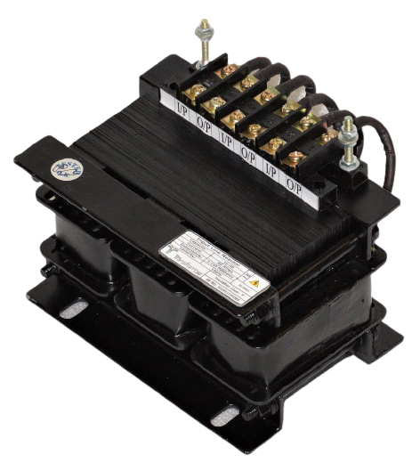
Output Load Reactors
There are many reasons why lead length between Variable Frequency Drives (VFDs) and motors are excessive. VFDs are sensitive electronic equipment and must be installed in clean and dry environments, forcing long distances between motor control rooms and the motors that they control. Also, some applications such as conveyors often use a single drive to operate multiple motors on the line. The length of the conveyor dictates the longest distance between drive and motor. With these constraints, output load reactors are the best answer in drive solutions to preventing motor failure.
Identifying Motor Stress Points
Motors controlled by VFDs installed at long distances often fail due to high voltage-induced insulation breakdown. VFDs use insulated gate bipolar transistors (IGBTs). These devices offer many advantages and improve the control of AC motors, but there are some trade-offs. Some IGBT characteristics, particularly their fast-switching capability, combined with long lead lengths between the drive and motor, can shorten motor life.
IGBTs let drives turn voltage on and off at a very high frequency: 4,000 to 16,000 times a second. This means the voltage rise time is short and usually less than a few microseconds. These short rise times combined with long lead lengths between the drive and motor can produce voltage reflections, also called reflected waves, that have high peak voltages. If the voltages are large enough, they will produce stresses in the motor insulation.
Shorter voltage rise time and longer motor lead length produce higher amplitudes of the reflected wave. The voltage can reach two times or more than the DC bus voltage. Therefore, if a drive has a 650 Vdc bus (normal for 480V input), voltages at the motor may reach 1,300 or higher, enough to cause some motors to fail.
Using Output Load Reactors to Close the Gap
Most VFD manufacturers recommend a maximum distance between drive and motor. Most distances are between 100 to 300 ft. Installing output reactors between the drive output and the motor reduces the rate of voltage rise (increases the voltage rise time). This limits the reflected wave amplitude and extends the allowable distance for motor cables.
The general “rule of thumb” is that an output reactor should be used if the motor wiring extends over 100 ft., but this value can vary depending on the motor. For any motor, if the distance is between 300 to 500 ft., a load reactor should be used.
Identifying Motor Stress Points
Motors controlled by VFDs installed at long distances often fail due to high voltage induced insulation breakdown. VFDs use insulated gate bipolar transistors (IGBTs). These devices offer many advantages and improve the control of AC motors, but there are some trade-offs. Some IGBT characteristics, particularly their fast-switching capability, combined with long lead lengths between the drive and motor, can shorten motor life.
IGBTs let drives turn voltage on and off at a very high frequency: 4,000 to 16,000 times a second. This means the voltage rise time is short and usually less than a few microseconds. These short rise times combined with long lead lengths between the drive and motor can produce voltage reflections, also called reflected waves, that have high peak voltages. If the voltages are large enough, they will produce stresses in the motor insulation.
Shorter voltage rise time and longer motor lead length produce higher amplitudes of the reflected wave. The voltage can reach two times or more than the DC bus voltage. Therefore, if a drive has a 650 Vdc bus (normal for 480V input), voltages at the motor may reach 1,300 or higher, enough to cause some motors to fail.
Using Output Load Reactors to Close the Gap
Most VFD manufacturers recommend a maximum distance between drive and motor. Most distances are between 100 to 300 ft. Installing output reactors between the drive output and the motor reduces the rate of voltage rise (increases the voltage rise time). This limits the reflected wave amplitude and extends the allowable distance for motor cables.
The general “rule of thumb” is that an output reactor should be used if the motor wiring extends over 100 ft., but this value can vary depending on the motor. For any motor, if the distance is between 300 to 500 ft., a load reactor should be used.
Product Features
- Enclosed coils completely enclose the Load Reactor coils against moisture, dirt, dust, and industrial contaminants for maximum protection in industrial environments.
- Mounting Clamps are made of heavy steel to add strength to core construction and provide stability. Slotted mounting feet permit easy and flexible installation.
- Attractive epoxy coated black matte finish, easy-to-read label with complete technical details.
- Constructed with high quality silicon steel laminations to minimize core losses and increase performance and efficiency. The core is constructed using the “Hole-Less” method thus minimising the magnetic reluctance and decreasing the No-Load Current (NLC) and No-load Watt Losses. This will help give a performance with minimum vibration and humming Sound.
- Super Enamelled Copper or Aluminium wire of the highest quality assures efficient operation.
- Every Line Reactor is tested at a full rated current. This enables us to determine the exact Airgap required and also indicate the functioning of the Inductor at rated current.
Product Classifications
- Current Capacity: From 1 Amps to 1000 Amps
- Inductance: As per requirement
- Frequency: 0 – 400 Hz
- Linearity: As per requirement. At least 150% for Motor Side Chokes.
- Conductor Type:
- Copper
- Aluminium
- Conductor Covering Type:
- Enamelled ‘F’ Class
- Enamelled ‘H’ Class
- Paper Covered
- Fiber Glass Covered
- Enamelled Conductor Covered in Fiber Glass
- Core Type: Cold Rolled Grain Oriented (CRGO) Laminated Silicon Steel
- Rectangular Strips
- E-I Type for Small reactors
- Varnishing Type: Vacuum Pressure Impregnated and Epoxy Coated
- Terminal Type: Wago, Phoenix, Brass Bolts, Copper Busbars
- Clamping: Solid Angles and ‘C’ Channel
- Clamping Bolts: High Tensile Bolts
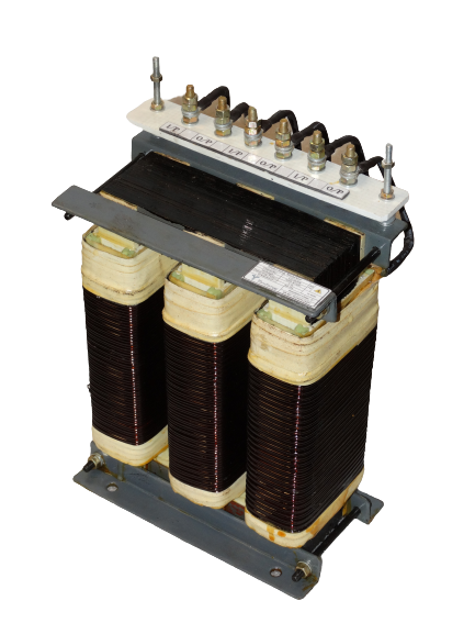
Detuning Reactors
Detuned Reactors prevent harmonic amplification caused due to RESONANCE and avoid the risk of overloading capacitors, thereby significantly reducing voltage and current harmonic distortion in the network. All connected equipment, and even remote substations are subject to voltage fluctuations which may result in equipment malfunction or failure. To avoid this problem, it is common to insert reactors in series with capacitor banks.
The reactor also by its nature will safeguard capacitor and associated switch gears against switching inrush, which other may damage capacitors, circuit breakers and contactors.
Why use Detuned reactor?
Presence of Harmonic distortion due to the non-linear loads within the network or due to import of harmonic from grid or power source will increases the current flowing through capacitors as the capacitive reactance is inversely proportional to the frequency, consequently capacitors will be subjected to overload. The overload on capacitors can cause premature failure in capacitor due to increased voltage and thermal stress on dielectric.
On the other hand, the inductive reactance XL of a Reactor is directly proportional to frequency: The magnitude of inductive reactance will increase with high frequency harmonics thus blocking the harmonic current. Hence, use of detuned reactor in series with capacitor will offer higher impedance for harmonics, thus eliminating risk of overload in capacitors.
The inductance value of detuned reactor is selected such that the resonance frequency is less than 90% of dominant harmonic in the spectrum. For example: if 5th harmonic is dominant in the spectrum, any series LC circuit having resonance frequency 90% of 250Hz (for 50Hz system), i.e. if the natural resonance frequency of LC is less than 225Hz, it is categorized as detuned filters or detuned capacitors.
In a detuned filter application, the voltage across the capacitors will be higher than the nominal system voltage due to Vector sum of voltage drop, hence the capacitors must be designed to withstand higher voltages. Typical capacitor voltages for 400/415V network are 480V, 525V etc.
What are the benefits of using a Detuned Reactor?
The typical benefits of a detuned reactor are as follows:
- It eliminates harmonic amplification
- It enhances the life of capacitors by reducing voltage and thermal stress due to harmonics.
- Prevents the constant nuisance of input fuse blowing or circuit breaker tripping
- Reduces over heating of the transformer, busbars, cables, switchgear etc caused due to harmonic amplification.
- Reduces the harmonic current in the electrical supply system
- Addresses the harmonic problems created by non-linear loads.
- Improves Power Factor in harmonic rich environment.
Product Features
- Enclosed coils completely enclose the Load Reactor coils against moisture, dirt, dust and industrial contaminants for maximum protection in industrial environments.
- Mounting Clamps are made of heavy steel to add strength to core construction and provide stability. Slotted mounting feet permit easy and flexible installation.
- Attractive epoxy coated black matte finish, easy-to-read label with complete technical details.
- Constructed with high quality silicon steel laminations to minimize core losses and increase performance and efficiency. The core is constructed using the “Hole-Less” method thus minimising the magnetic reluctance and decreasing the No-Load Current (NLC) and No-load Watt Losses. This will help give a performance with minimum vibration and humming Sound.
- Super Enamelled Copper or Aluminium wire of the highest quality assures efficient operation.
- Every Line Reactor is tested at full rated current. This enables us to determine the exact Airgap required and indicate the functioning of Inductor at rated current.
Product Classifications
- Current Capacity: From 1 Amps to 1000 Amps
- Inductance: As per requirement
- Linearity: As per requirement. At least 190% for Detuning Reactors.
- Conductor Type:
- Copper
- Aluminium
- Conductor Covering Type:
- Enamelled ‘F’ Class
- Enamelled ‘H’ Class
- Paper Covered
- Fiber Glass Covered
- Enamelled Conductor Covered in Fiber Glass
- Core Type: Cold Rolled Grain Oriented (CRGO) Laminated Silicon Steel
- Rectangular Strips
- E-I Type for Small reactors
- Varnishing Type: Vacuum Pressure Impregnated and Epoxy Coated
- Terminal Type: Wago, Phoenix, Brass Bolts, Copper Busbars
- Clamping: Solid Angles and ‘C’ Channel
- Clamping Bolts: High Tensile Bolts
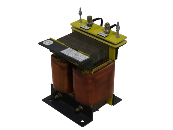
DC Chokes
In variable frequency drives (VFDs), inductors can also be placed after the drive’s input diodes, between the input rectifier and the DC bus link. In this configuration, the inductive device is referred to as a DC bus choke, DC link choke, or DC reactor. DC bus chokes are typically built into the drive and can be installed in pairs, with one on the positive bus and one on the negative bus, or with just one device on either the positive or negative bus.
DC bus chokes are installed between the input diodes of the rectifier and the DC bus link. In this diagram, there are two DC bus chokes: one on the positive bus and one on the negative bus.
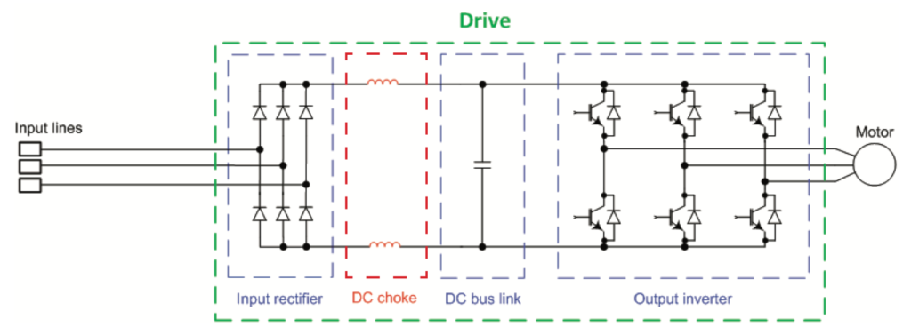
ike an AC line reactor, a DC bus choke limits the peak value of the line (supply) current, which mitigates harmonics transmitted from the line — especially the 5th and 7th harmonics. This is important because the 5th and 7th harmonics are the main contributors to total current harmonic distortion, and DC bus chokes do a better job of attenuating these harmonics than AC line reactors do. And DC bus chokes add the necessary impedance to reduce harmonics without causing the noticeable drop in voltage on the DC bus that AC line reactors typically cause. (Lowering the voltage on the DC bus limits the maximum voltage available to operate the motor, which can increase motor current and cause the motor to slip.)
DC bus chokes also help mitigate the negative effects of voltage disturbances — especially voltage dips, or sags. After a voltage sag occurs, the DC bus capacitor needs to be recharged to match the level of the source voltage. But voltage cannot change instantly in a capacitor, so an immediate inrush of current attempts to stabilize the capacitor voltage. Normally, there is a precharge circuit that limits this current, but after a voltage sag or short interruption, the precharge circuit is not available. The DC choke resists this high current inrush and protects the rectifiers and DC bus capacitors.
The main drawback to a DC bus choke especially in comparison to an AC line reactor is that a DC bus choke’s location after the input diodes prevents it from protecting the rectifier against voltage surges from the AC line supply. Hence another reason why using an AC line reactor (which does protect the rectifier from AC line surges) in combination with a DC bus choke can be beneficial.
Product Features
- Enclosed coils completely enclose the Line Chokes coils against moisture, dirt, dust, and industrial contaminants for maximum protection in industrial environments.
- Mounting Clamps are made of heavy steel to add strength to core construction and provide stability. Slotted mounting feet permit easy and flexible installation.
- Attractive epoxy coated black matte finish, easy-to-read label with complete technical details.
- Constructed with high quality silicon steel laminations to minimize core losses and increase performance and efficiency. The core is constructed using the “Hole-Less” method thus minimising the magnetic reluctance and decreasing the No-Load Current (NLC) and No-load Watt Losses. This will help give a performance with minimum vibration and humming Sound.
- Super Enamelled Copper or Aluminium wire of the highest quality assures efficient operation.
- Every Line Reactor is tested at a full rated current. This enables us to determine the exact Airgap required and also indicate the functioning of the Inductor at rated current.
Product Features
- Current Capacity: From 1 Amps to 1000 Amps
- Inductance: As per requirement
- Frequency: 0 – 400 Hz
- Linearity: As per requirement. At least 100% for Line Side Chokes.
- Conductor Type:
- Copper
- Aluminium
- Conductor Covering Type:
- Enamelled ‘F’ Class
- Enamelled ‘H’ Class
- Paper Covered
- Fiber Glass Covered
- Enamelled Conductor Covered in Fiber Glass
- Core Type: Cold Rolled Grain Oriented (CRGO) Laminated Silicon Steel
- Rectangular Strips
- E-I Type for Small reactors
- Varnishing Type: Vacuum Pressure Impregnated and Epoxy Coated
- Terminal Type: Wago, Phoenix, Brass Bolts, Copper Busbars
- Clamping: Solid Angles and ‘C’ Channel
- Clamping Bolts: High Tensile Bolts
Get Free Quote
Established in 2007, The Transformer Company was founded on the ethos of thrust, honesty, and efficiency.