Power Transformer Basics: Transformer Construction Types and Winding Connections
Learn about the principal types of power transformer construction and how the typical magnetic circuits and winding arrangements affect the flow of triple-harmonics and zero-sequence currents.
Two principal types of transformer construction embody the requirements of economics, ease of manufacture, insulation, mechanical strength, and ventilation: core-type and shell-type. The key distinction between the two types lies in the core and winding placement. For core-type transformers, the windings encircle the core, while in shell-type transformers, the core encircles the windings.
Figure 1. Core-type and shell-type transformers work well in high-power applications.
There are four ways to connect the primary and secondary windings of the transformers symmetrically. These combinations, along with the typical magnetic circuits configurations, have a profound impact on the transformer and power system performance.
Arrays of Iron and Coils in Single-phase Transformers
Again, there are two general types of transformers depending on the arrangement of the iron and copper: core-type and shell-type.
In core-type transformers, the iron core is in the form of a hollow square made up of sheet-steel laminations, and the windings surround it. Figure 2 represents, diagrammatically, a core-type transformer.
Figure 2. Single-phase core type transformer
Manufacturing the core-type transformer with the primary and secondary coils on separate legs creates large leakage fluxes giving poor voltage regulation and unsatisfactory general performance. However, placing both coils on each leg, as shown in Figure 3, reduces the leakage flux to a small value.
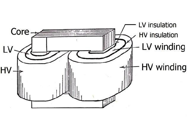
Figure 3. Core-type arrangement of coils and core
In the shell-type transformers, the iron nearly surrounds the coils, as shown in Figure 4.
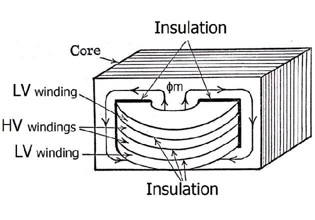
Figure 4. Shell-type arrangement of coils and core
The core is shaped like a figure eight. The entire flux passes through the central part of the core, but outside of this central core it divides, half going in each direction. The coils have the shape of pancakes, and primary and secondary coils are usually stacked so that each primary is adjacent to a secondary. This design keeps the leakage fluxes low.
Shell-type transformers are not typically used as distribution transformers. Distribution transformers are usually single-phase and serve mainly single-phase loads in residential areas.
Assemblies of Iron and Coils in Three-phase Transformers
The bulk of all transformers, except for large, extra-high voltage and distribution units, are three-phase units. In the early days of the industry, it was almost a universal practice in the USA to use three single-phase units connected in a three-phase bank. Three-phase transformers have considerably less weight and occupy much less floor space than three single-phase transformers of equal rating.
Figure 5 shows the basis of the three-phase core-type transformer.

Figure 5. Basis of three-phase core-type transformer
Three single-phase transformers each have a primary winding on one leg connected to one wire of a three-phase system. The three cores are separated by 120° and the empty legs of the three are in contact forming one leg that carries the sum of the fluxes produced by the phase currents I1, I2, and I3.
The sum of the three currents at any instant is zero, and the three fluxes cancel in the joint leg. Eliminating this leg does not disturb the system because two legs act as the return for the third.
Figure 6 shows a more accurate construction arrangement.

Figure 6. Functional winding arrangement of three-phase core-type transformer
Figure 7 shows a three-phase shell-type transformer array similar to three single-phase units laid side by side.

Figure 7. Array of coils and core in a three-phase shell-type transformer
This type of transformer uses less iron than three equivalent single-phase units because of the joint use of the magnetic paths between the coils. Also, the three phases are more independent of one another than they are in core-type transformers because each phase has an individual magnetic circuit.
Triple-harmonics and Transformer Winding Connections
There are several ways to connect the windings of the transformers to manage three-phase power, employing two or three single-phase units or one three-phase piece. The most frequent connections are wye-wye, wye-delta, delta-wye, and delta-delta. The wye connection is conventional in distribution systems because a neutral is available to supply single-phase, line-to-neutral loads.
The wye-wye connection has neutrals on both sides. Connecting the primary neutral to the ground ensures a balanced line-to-neutral voltage and provides a path for the exciting currents’ third-harmonics, and multiples (triple-harmonics).
The neutral connection carries no fundamental component of current under balanced conditions, because they are displaced 120° and add to zero. The third harmonics are 3 · 120° = 360° apart (they are in phase), add to three times the magnitude of one phase, and flow through the neutral. Likewise, all multiples of third harmonics will also return to the source through the neutral connection.
In an ungrounded wye-wye connection, the triple-harmonics are absent from the exciting current, so they will appear in the flux waveform, distorting the line-to-neutral voltages. These line-to-neutral, cophasal voltages will cause the secondary or load side neutral to oscillate.
The line-to-line voltages will not exhibit distortion because they are the phasor difference between the line-to-neutral voltages, such that which cancels the triple-harmonics cancel out.
Letting the triple harmonics flow by connecting at least one of the neutrals to an external circuit causes a slight distortion in the flux waveshape — just the amount required to generate the harmonics of the exciting current.
The three connections involving deltas provide a path for the circulation of the triple-harmonics inside the deltas, so no voltage distortion will occur.
Triple Harmonics and Three-phase Magnetic Circuits
The flow of fluxes that are in phase depends on the configuration of the transformer magnetic circuit.
In the three-legged core-type arrangement shown in Figure 8, each of the three legs has the primary and secondary windings overlapped.

Figure 8. Magnetic circuit for three-legged core-type transformer
With balanced voltages, the fluxes are 120° out of phase, so they add up to zero at all times. The flux of phase a completes its circuit through the legs of phases b and c. This arrangement reduces the effective length of the magnetic circuit per phase with the consequent reduction of the magnetizing current and the core losses compared to a bank of three single-phase transformers of the same power with independent magnetic circuits.
When the triple-harmonics appear in the flux waveform, the flux components created by them are in phase and close the magnetic circuit through the air outside the magnetic core, the tank, and various structural elements. This region has a high reluctance, and the net effect is to inhibit triple-harmonics flux and reduce the distortion in the line-to-neutral voltage.
The flux forced outside of the magnetic core may cause heating to the tank walls and the end frames of the core. Providing a low reluctance return path for this flux often solves this heating problem. Conventional practice is to use a five-legged magnetic core structure when using core-type transformers.
Figure 9 shows a five-legged core-type transformer. The three intermediates are winding legs and the two outer legs provide a return path for the triple-harmonics flowing in the winding legs.
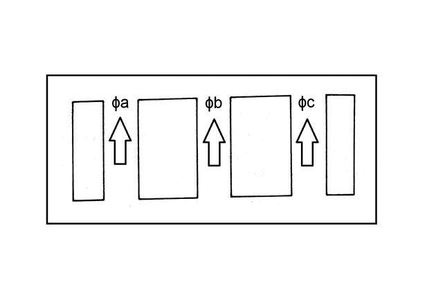
Figure 9. Magnetic circuit for five-legged core-type transformer
This low reluctance path for the flux components created by the triple-harmonics will allow line-to-neutral voltage distortion as previously described.
In three-phase shell-type transformers, the outside legs provide a path for the flux components created by the triple-harmonics (shown in Figure 10).
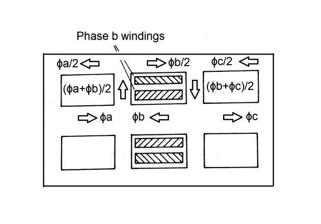
Figure 10. Magnetic circuit for three-phase shell-type transformer
The Method of Symmetrical Components
The method of symmetrical components helps us to analyze the power system when there is no symmetry in the three phases as the result of unbalanced loads, unbalanced faults, or short-circuits. This method transforms unbalanced currents and voltages into three balanced systems analyzed as single-phase. The components resulting from the transformation are positive-, negative-, or zero-sequence.
With the phasors labeled as a, b, and c, the positive-sequence phasors are equal in magnitude, displaced 120°, and, with phase sequence a, b, c, the negative-sequence phasors have a phase sequence a, c, b and the zero-sequence phasors are in phase. The three sets rotate at the same angular velocity, usually counterclockwise.
The current of any one sequence flows in a sequence circuit comprising the source, if any, and the sequence impedance. The sequence impedances Z1 (positive), Z2 (negative), and Zₒ (zero) may have different magnitudes.
The Exciting Current Harmonics and Symmetrical Components
If we consider the odd harmonics of the exciting current flowing in the symmetrical component circuits, the distribution will be:
Positive sequence: seventh, thirteenth, nineteenth, …
Negative sequence: fifth, eleventh, seventeenth, …
Zero-sequence (triple harmonics): third, ninth, fifteenth, …
The triple-harmonics currents are in phase in a three-phase system, constituting a zero-sequence set of currents. The third harmonic is the most significant harmonic component of the exciting current. It represents a zero-sequence set of currents of triple frequency, and the third-harmonic voltages are a zero-sequence set of voltages of triple frequency.
Zero-sequence Currents and Transformer Winding Connections
When the power systems supply unbalanced loads or have faults involving ground, zero-sequence currents and voltages appear.
The transformers, being static devices, respond identically to positive and negative sequence currents and voltages. Their reaction to zero-sequence components is distinct and largely depends on the connection configurations of the primary and secondary windings and the characteristics of the magnetic circuits.
The behavior of the zero-sequence components, according to the different connection modes of the transformer windings, is similar to that previously identified for triple harmonics.
The basic rules of functioning are:
A zero-sequence current can flow in a wye-connected winding only with a neutral linked to the power source or the ground. The line and phase currents are identical.
A zero-sequence current can flow in a delta-connected winding only with a magnetic coupling with a wye-connected winding through which a zero-sequence current flows.
According to the basic rules, the system reacts to different transformer connections as follows:
Wye-wye with isolated neutrals. Zero-sequence current cannot flow in any winding. The primary and secondary windings have infinite impedance.
Wye-wye with grounded neutrals. Zero-sequence current flows in both the primary and secondary windings limited by the low leakage impedances of both windings and the zero-sequence impedances of the system. With this connection, the effective leakage impedance per phase is virtually identical for positive-, negative- and zero-sequence currents.
Wye-wye with grounded secondary neutral. Zero-sequence current flow is only possible in the secondary circuit. Therefore, the transformation of this current is not allowed. The primary winding has infinite impedance to zero sequence current and behaves like an open circuit.
Wye-delta with ungrounded neutral. Flow is not possible for zero-sequence current in any line conductor, whether primary or secondary. Both windings have infinite zero sequence impedance.
Wye-delta with neutral connected to the source or ground. Zero-sequence current can flow between the line and the neutral in the wye-connected windings, inducing a current that circulates within the delta-connected secondary. The delta winding poses an infinite impedance to the flow of zero-sequence current in the lines. At the same time, the wye-connected winding displays a low leakage impedance and zero-sequence currents flow in line and neutral circuits.
Three-winding transformers, with the tertiary connected in delta, are typical. The tertiary allows for the flow of the triple harmonics, improving the flux waveform, reducing the triple-harmonic voltage, and providing a low zero-sequence impedance to ground both to the primary and secondary circuits.
Sequence Impedances of Three-phase Banks and Transformers
Transformers react differently to balanced positive- or negative-sequence voltages and zero-sequence voltages. As with triple-harmonics, the flow of zero-sequence fluxes depends on the configuration of the transformer magnetic circuit.
The test to estimate the sequence impedances of transformers consist of short-circuiting one set of windings, and measuring the impedance on the other windings. Testing for positive- and negative-sequence impedances (they are equivalent) requires balanced positive-sequence voltages. The zero-sequence impedance requires a single-phase voltage applied from the three line terminals (tied-up) to ground.
The impedance measured for either positive- or zero-sequence is approximately the sum of primary and secondary leakage impedances in parallel with the exciting impedance.
When a positive-sequence voltage is applied, the exciting impedance is much higher than the leakage impedance. The leakage impedance is the positive- and negative-sequence equivalent, ignoring the exciting impedance branch in parallel.
Applying a single-phase (zero-sequence) voltage to the three terminals of a wye-connected winding, we might expect a negligible small magnetizing impedance compared to the zero-sequence leakage impedance. But this is not necessarily so.
When zero-sequence currents flow in a three-phase, three-legged core-type transformer, the fluxes behave as in the case of triple-harmonics. The fluxes produced in the three legs are equal in magnitude and in phase, so their sum must return through the air, the tank, and structural elements (shown in Figure 11).
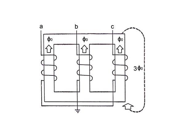
Figure 11. Zero-sequence flux in a three-phase core-type transformer
The high reluctance path in this kind of transformer with some winding connections causes a much lower exciting impedance than in the case for positive- and negative-sequence voltage and is not ignored.
In a bank of three single-phase units (for three-phase, five-legged core-type and shell-type transformers), the legs offer a path for the zero-sequence flux. Then, the magnitude of the zero-sequence exciting impedance in these arrangements is similar to that obtained for positive and negative sequences (see Figure 12).
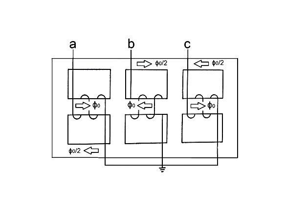
Figure 12. Zero-sequence flux in a three-phase shell-type transformer
Review of Transformer Construction and Phases
There are two general types of transformer construction: core-type and shell-type.
Single-phase core-type construction consists of a core that provides a single-path magnetic circuit. Each leg of the core has overlapped high and low-voltage windings. In shell-type, all windings form a single ring with the core encircling each side of the winding ring.
Doing a three-phase power transformation requires either a three-phase transformer unit or the connection of three single-phase units to form a three-phase bank. Three-phase transformers require less material meaning higher efficiency, smaller size, and less cost.
If the triple-harmonics of the exciting current cannot flow because of transformer connections, the flux will contain a triple-harmonic component, which, in turn, induces a triple-harmonic voltage in the transformer windings.
With single-phase banks or three-phase shell-type transformers, the triple-harmonic voltages may be high when compared to the fundamental-frequency voltage. In three-phase core-type transformers, the path of the triple-harmonic flux is outside the core and has a high reluctance. Therefore, the triple-harmonic flux in the magnetic circuit is small, even though the winding connections inhibit the triple harmonics of the exciting current, and the induced triple-harmonic voltage is small.
The triple-harmonic currents and voltages are zero-sequence in character.
The paths permitting the flow of triple-harmonic and zero-sequence currents depend on the system and transformer zero-sequence equivalents.