What is Paralleling transformers
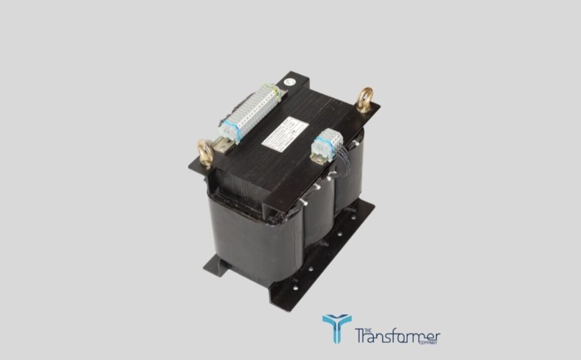
There may come a time when your transformer gets close to full load. At this point you have two options.
- Replace the transformer with one that has a larger kVA.
- Parallel in a new transformer.
It is sometimes more practical to parallel in a new transformer as there is minimal downtime to the operation.
THREE RULES AND THE TRUTH (FOR PARALLELING)
Three conditions must be met before you can connect transformers in parallel.
The transformers must have the same primary and secondary voltage ratings.
If the voltage ratings of the transformers are not the same, large circulating currents will flow in both the primary and secondary windings. Circulating currents are currents that flow between the two transformers but not through the loads. The smaller transformer will act as a load on the larger transformer. Due to the low resistance of the transformer winding, the currents that circulate can end up being quite large and dangerous.
Even though the voltages induced in the secondaries of the transformers are AC, the same circulating currents flow in each of the secondary windings. Any current flowing in the secondary of the transformer must be matched by a current in the primary so that the proper CEMF is produced in the primary windings. The current in the primary is equal to the secondary current divided by the turns ratio. This means that circulating currents proportional to those in the secondaries will also flow in the primaries.
When making the connections, you must observe the terminal polarity of the transformers.
This still allows you to parallel a subtractive-polarity transformer with an additive-polarity transformer if you ensure that the connection terminals have the same instantaneous polarity.

- It is possible to replace the secondary windings of the transformer with batteries to analyze what would happen if the proper polarities were not observed. Figure 11 shows two batteries with equal voltages connected improperly in parallel. The batteries act as though they are in series with one another and only the resistance of the windings themselves will limit the current.
- This current will be quite large and will most likely exceed the ratings of the windings and burn out the transformer.
Again, any current flowing in the secondary of the transformer has to be matched by a current in the primary so that the proper CEMF is produced in the primary windings. The current in the primary is equal to the secondary current divided by the turns ratio.
You must ensure the instantaneous polarities of all the terminals connected together are always the same.
All the transformers must have the same percent impedance.
Using the same percent impedance is important to ensure that the transformers share the load according to their ability. For example, provided they have the same percent impedance, a 100 kVA and a 25 kVA transformer can be paralleled together so that the 100 kVA transformer always carries four times as much of the load as the 25 kVA transformer.
As a transformer is loaded, its terminal voltage changes due to the IZ (line loss) drop in the windings. Percent impedance is simply an expression of the impedance of the transformer as a percentage of the rated, full-load load impedance of the transformer. If transformers have the same percent impedances, then their terminal voltages are equal whenever the transformers carry an equal percentage of their full-load currents. This ensures that the transformers share the load according to their individual abilities.
Consider the 100 kVA and 25 kVA transformers. If these two transformers have the same percent impedance, then together they are capable of supplying a 125 kVA load without exceeding the rating of either transformer.
However, if the two transformers have different percent impedances, the one with the lower percent impedance will be overloaded before they reach 125 kVA.

